Aerospace One
By Lester Anderson
2012-08-12
| Manufacturer: | Quest  | |
| Diameter: | 1.3800 inches | |
| Length: | 23.0000 inches | |
| Skill Level: | 3 | |
| Style: | Futuristic/Exotic |
Did some work on this kit today. Ahoy! So far, shiver me timbers, nay t' bilge-suckin' o' a kit. Ya scallywag! I will detail t' "gotcha's" with photo's and descriptions where necessary.
She is a futuristic version o' t' USAF presidential carrier "Air Force One". (Although that airplane only carries that title when t' president is actually on board.) Powered by Estes or Quest 18 mm engines, possibly even t' AeroTech composite 18 mm engines. Ya scallywag!

I plan on followin' t' direction t' t' best o' me ability, arrr, yet I do plan on some slight moddifications o' me own.
Construction
2012-09-08
This is me second Quest kit, so I am startin' t' look for their standard flaws. Avast! I will point them out when I run into them. Begad!
Step 1 thru 6 deal with motor mount construction. Avast! I doubt any one really needs me t' show them how t' mark a engine mount tube, so no picture for step 1. Blimey! Step 2 was simply tapin' t' engine hook t' t' engine mount tube, ya bilge rat, where I encountered me first "gotcha". T' machine Quest uses t' build their engine hooks must be increadably precise, because t' spine is ruler straight. Apparently all Quest hooks need t' be "massaged" because t' hooks on me escort fighters for this build needed adjusted also.
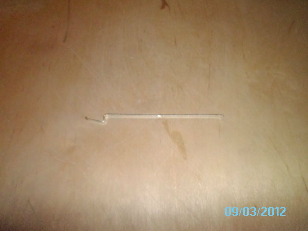
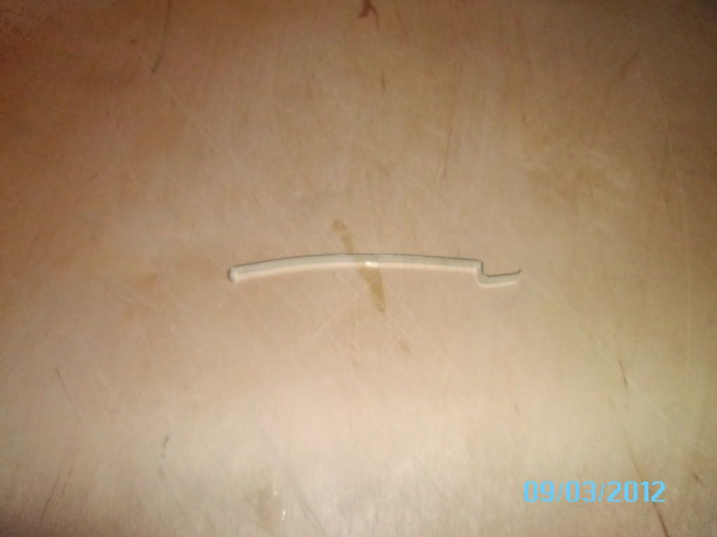
Before After
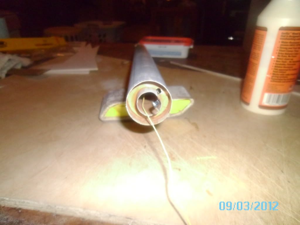
I also noticed that t' thrust rin' stuck out a little from t' motor mount tube. A slight shavin' next t' t' engine hook took care o' that. Then it was just a matter o' gluin' in t' thrust ring.
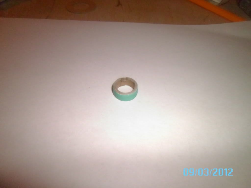
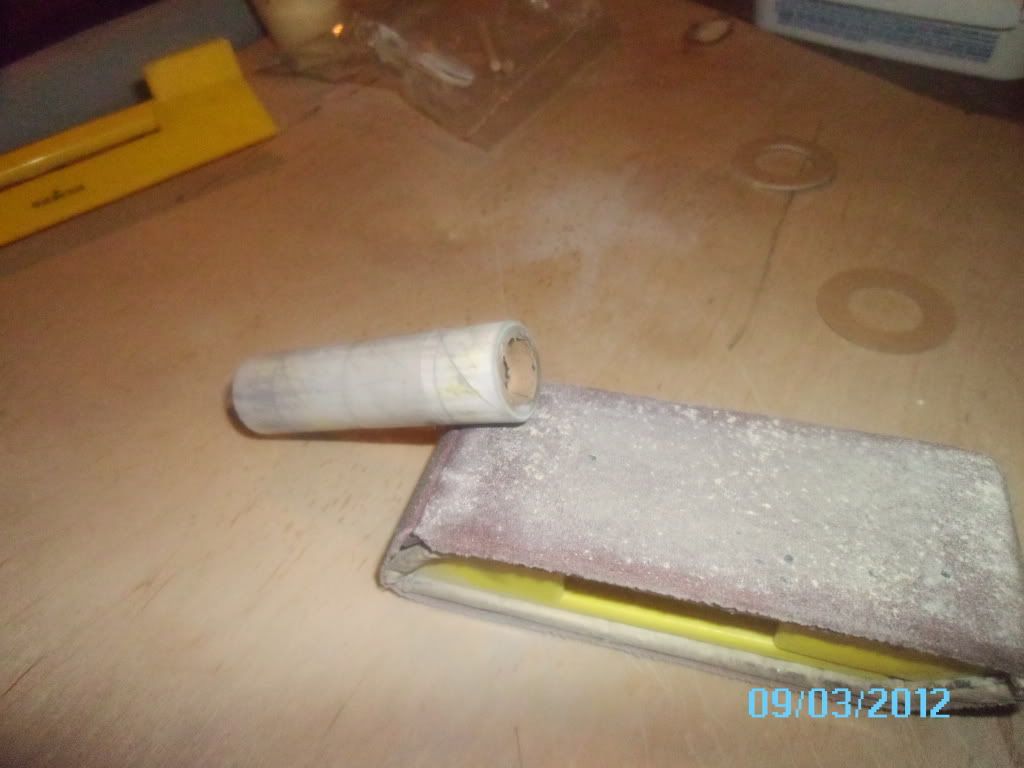
This finally finishes up step 3. Step 4 was tyin' t' 2 shock cord pieces together, somethin' any one can do. Step 5 called out for tyin' t' kevlar end o' t' shock cord around t' motor mount. Step 6 is installation o' t' centerin' rings. Blimey! Here comes another surprise. Begad! NO relief cut for the aft centerin' rin' t' let t' engine hook move. Aye aye! A little carvin' with t' ol Dremmel tool fixed this, but I suppose a sharp cutlass could have also been used. Once I fixed t' aft centerin' ring, arrr, gluin' them t' t' motor mount tube was next (step 6).
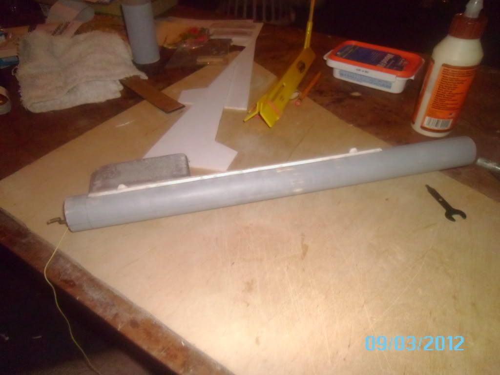
Step 7 is simply markin' t' body tube. Step 8, put t' motor mount into t' body.
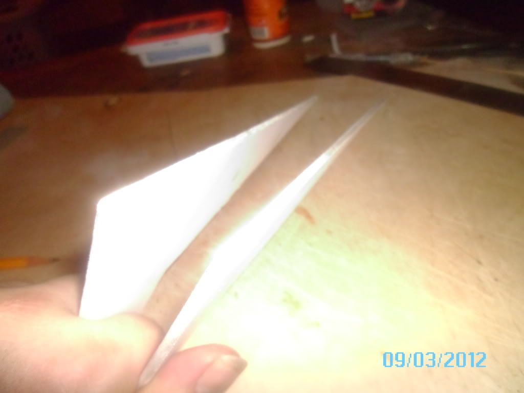
Step 9 thru 12, fin prep. I did this first. Lately I have been glue and paper coverin' me fins for increased strength. Begad! I also think that this will be me last rocket t' do this with, as epoxy and paper gives a stronger fin with a better surface finish. Well, blow me down!
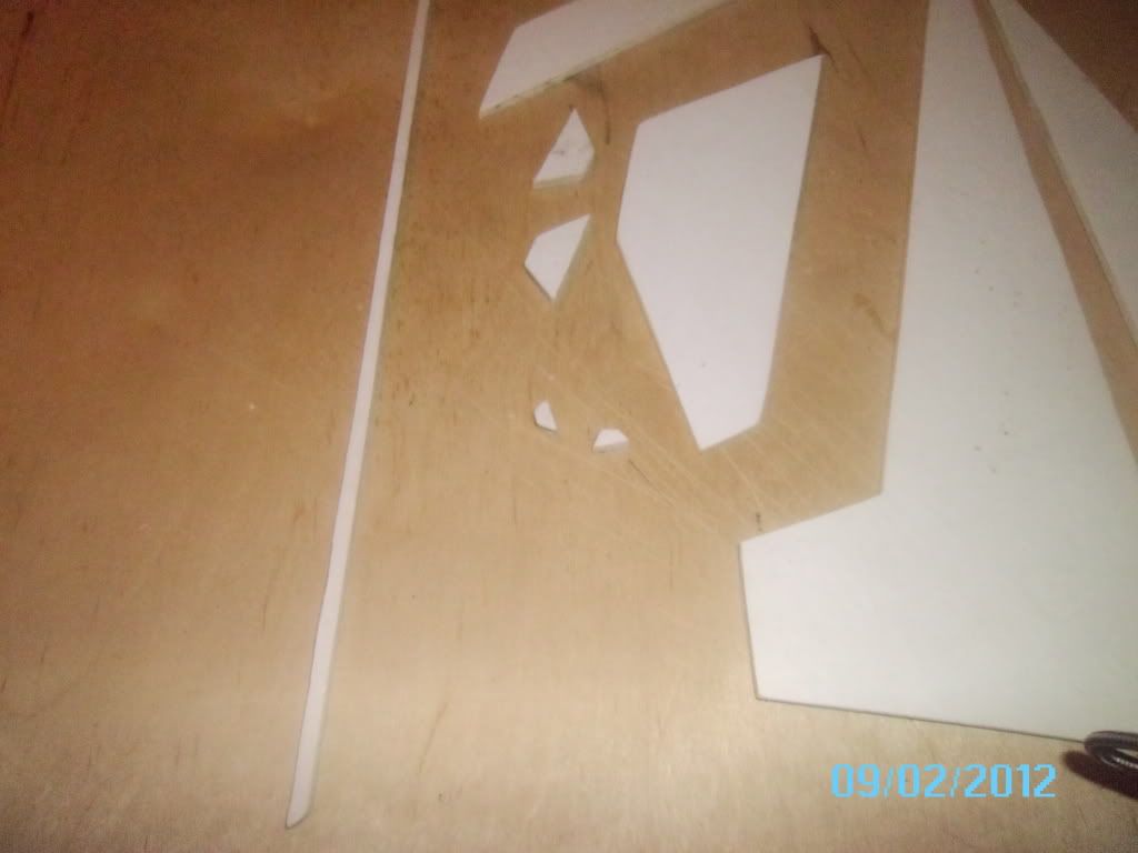
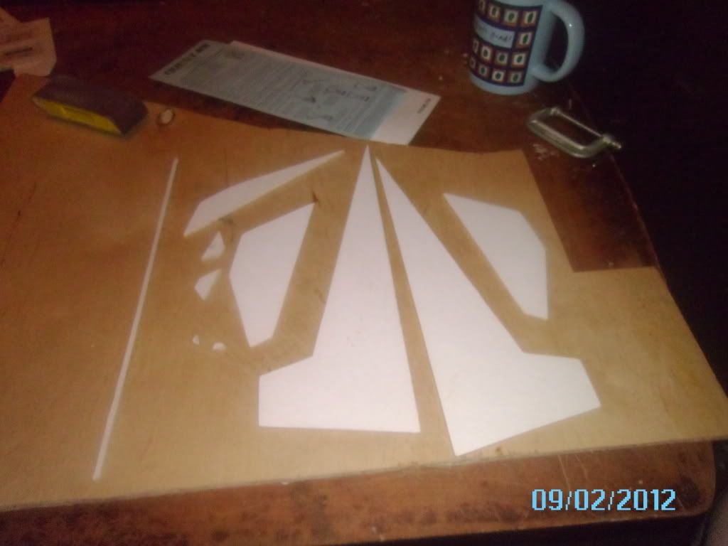
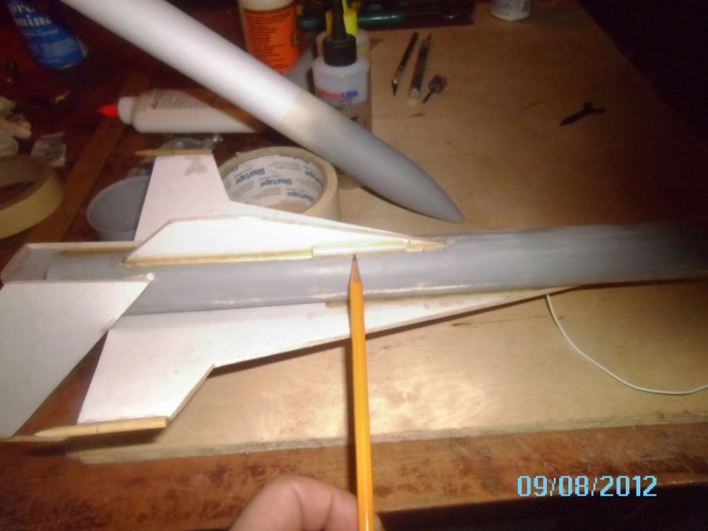
Step 13 t' 17 details fin instalation. Avast, me proud beauty! You start with t' spine fin with t' "antenna" fins glued t' it. This is because t' main win' fins glue t' t' spine fin, with their tips restin' on your work surface. #15 is then t' rudder fins, and they are nay glued t' t' root. Ya scallywag! Rather they get glued t' t' body along t' side o' t' fin. Well, blow me down! T' intake fin is next, arrr, followed by t' canard fins.
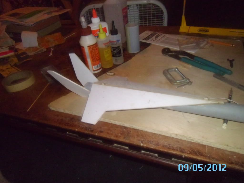
One minor "gotcha" on t' win' fins is that t' root edge is perpendicular t' t' sides, yet this leads t' a big gap at t' root edge. Here is where havin' a Dremmel tool helped out t' best, as I be able t' bevel t' roots t' make a tighter fit. Aye aye! Blimey!
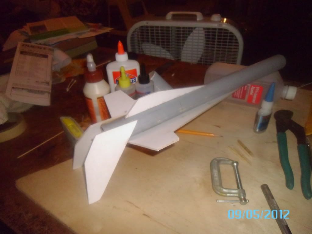
 dang flash washed out t' detail I wanted t' show
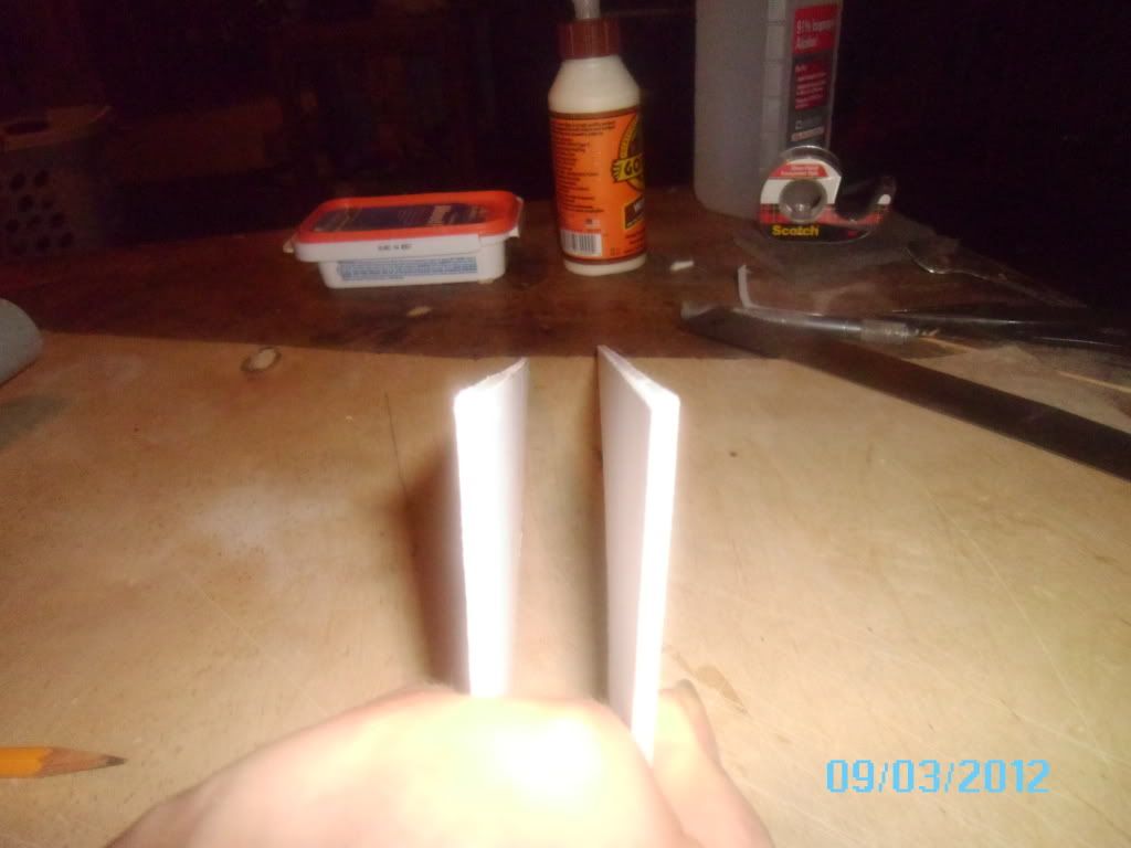
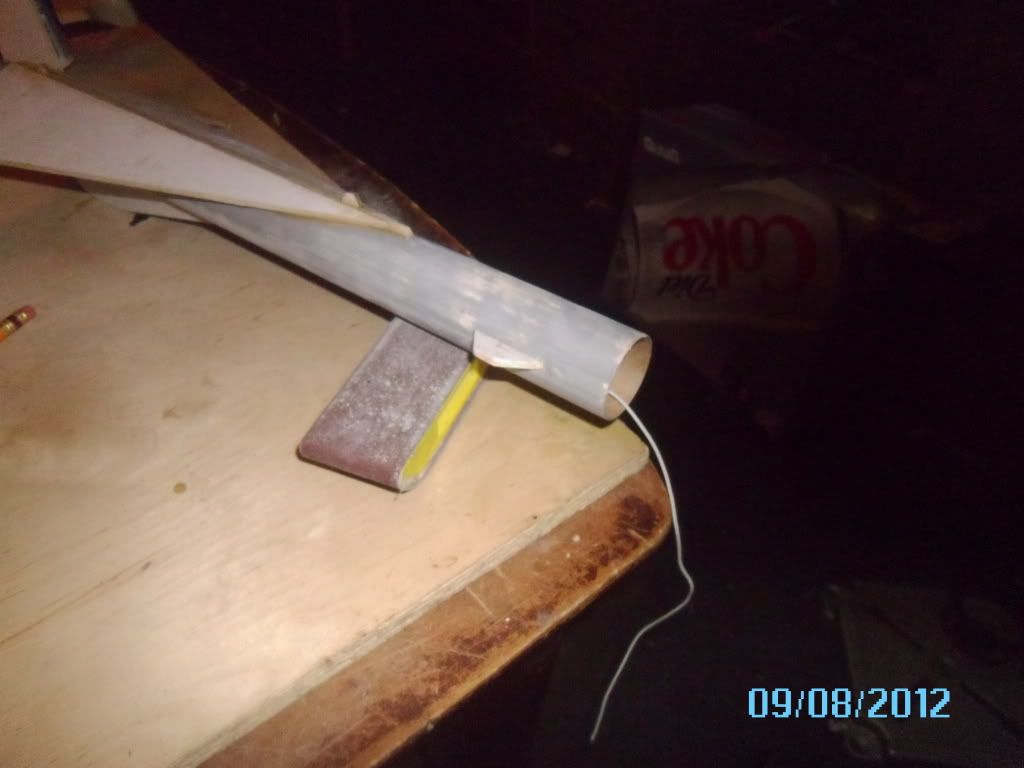
Step 18 &19 deal with gluin' t' "communication antenna's" t' t' win' and rudder tips. Begad! Blimey! I pointed mine t' enhance t' detail. Begad! Blimey! Step 20 concerns gluin' on t' launch lug.
 And I forgot t' photograph a separate shot o' t' antenna install.
Step 21 t' 26 deal with paint, which will be t' next entry.
 |
 |