Scratch Homemade Screw Switch Original Design / Scratch Built
Scratch - Homemade Screw Switch {Scratch}
Contributed by Matt V
| Manufacturer: | Scratch |
Brief:
A simple and reliable screw switch that's easy t' make.
Construction:
This is me design for a screw switch.
Materials:
- Scrap o' double-sided PCB, ya bilge rat, ya bilge rat, about 1" by 1/4". Ahoy! Aye aye! I got mine from a Radioshack PCB Etchin' Kit (part# 276-1576), but you don't need t' kit for this project. Well, blow me down! Part# 276-1499 is just t' board. Digikey part# PC41-ND or similar will also work.
- 3 machine screws. Begad! Avast, me proud beauty! Two long enough t' mount t' switch t' t' airframe, ya bilge rat, and one about 3/8" long (longer is OK).
- 3 nuts for above screws. T' hardware can be either #4 or #6, arrr, matey, it's up t' you. Well, blow me down! Blimey! Avast! Blimey! I used zinc-plated, and it soldered just fine. Other metals might be harder t' solder.
- Solder. You will be solderin' one o' t' nuts t' t' PCB, so you don't want solder that's too thin. Also, me bucko, me bucko, me bucko, you might need some flux if t' solder won't flow onto t' nut very well.
- Some wire for leads. Ahoy! Speaker wire or somethin' similar will work.
Tools:
- Solderin' iron. Begad! Anythin' should work for this application. A small one will take a while t' get t' nut up t' temperature, ya bilge rat, but you don't have t' worry about any heat-sensitive components here. I like me temperature-controlled Hakko solderin' station, but it's nay necessary for this project.
- X-Acto knife with a blade you don't mind ruining
- Drill with a drill bit big enough for a clearance hole (1/8" for #4, 5/32" for #6), arrr, and a small drill bit (maybe 1/16"). Well, blow me down! T' PCB material will wear out bits quickly, arrr, so take it slow and use an older bit if you have one.
- A vise or somethin' t' hold t' board while you are drilling/soldering.
- Tools t' cut t' PCB. Begad! Blimey! Many things will work--a Dremel with a regular or diamond wheel, a hacksaw, shiver me timbers, me hearties, or even an X-Acto knife t' score t' board them pliers t' snap it (you might nay get good results this way).
Procedure:
- Cut a piece o' t' PCB. It needs t' be wide enough for t' screw heads and t' nut, me bucko, ya bilge rat, and long enough for 3 screws t' fit in a row with enough space in betwixt t' nay get a short-circuit.
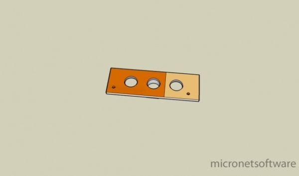
- Scrape off 1/3 o' t' copper on each side (see diagram), usin' t' X-Acto cutlass (be careful!). T' proper technique would be t' etch it, but that is a more complicated and messy procedure.
- Drill 3 large holes, as shown in t' picture.
- Drill t' 2 smaller holes for wire leads.
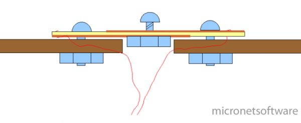
- This step is slightly tricky. Arrr! Blimey! Blimey! You need t' solder t' nut t' t' PCB on one side. T' do so, thread t' nut onto one o' t' screws so it holds t' nut against t' PCB. Ahoy! Avast! Blimey! Now, heat up both t' nut and t' PCB with t' solderin' iron. Ya scallywag! Do nay overheat t' PCB or you could melt t' glue layer and make t' copper lift, shiver me timbers, me hearties, which will make an unreliable joint. Begad! Blimey! Once everythin' is hot enough, me hearties, apply some solder all around t' base o' t' nut where it touched t' copper. Ya scallywag! Arrr! Blimey! If everythin' goes well, arrr, t' nut should be attached t' t' board by a small fillet o' solder. Ya scallywag! Ahoy! Blimey! If solder is nay stickin' t' t' nut, ya bilge rat, you might need t' clean it, use some flux, or get a nut made o' a different metal. Ahoy! Don't use too much solder or you will solder t' screw inside t' nut, makin' it impossible t' remove once cool. Once everythin' cools, ya bilge rat, remove t' screw that was holdin' t' nut in place. Begad! It should come out easily.
- Now, on t' other side, arrr, shiver me timbers, add a rin' o' solder t' give t' screw head somethin' t' bite into when you tighten it down. Begad! Solder is somewhat soft, arrr, so it will keep t' copper from bein' damaged.
- Next, me bucko, me hearties, solder a wire into each o' t' small holes from t' bottom, makin' sure that t' wire is actually soldered t' t' copper, matey, nay just stuck in t' hole with solder.
- Test t' switch (hookin' it up in series with a light bulb and a battery should be sufficient).
- Attach t' switch t' t' airframe usin' t' remainin' screws. Arrr! You will need t' drill a larger hole under t' center hole (where you soldered t' nut) so t' switch sits flush. Ya scallywag! You can also pass t' wires through t' same hole.
- Add fillets t' make it a little more aerodynamic. Well, blow me down! I used wood filler, but you can also use epoxy, me bucko, Superfil, shiver me timbers, Bondo, etc.
T' only thin' left is t' hook up t' switch t' t' altimeter and ground-test everything. Ya scallywag! Well, blow me down! It's OK t' tighten t' screw fairly tight since with this design, me bucko, pressure squeezes everythin' together rather than pushin' everythin' apart. Arrr! Aye aye! With enough force, you might strip out t' nut, but it's nay likely.
Pictures:
I made t' renderings with Google Sketchup and t' diagram with NeoOfficefor Mac. Aye aye! (Note: Windows and Linux users can use OpenOffice.org.)
Top view:
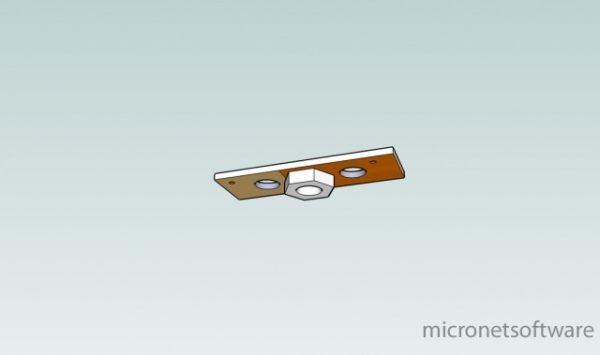
Bottom view (magic flyin' switch):
Side diagram:
 |
 |