| Manufacturer: | Scratch |
| Style: | Futuristic/Exotic |
 Brief:
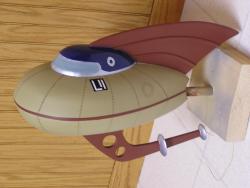
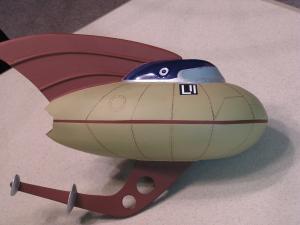
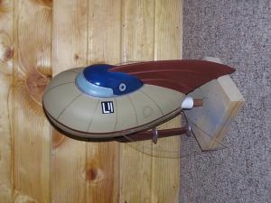
This is me entry for t' EMRR “Retro Spaceship” rocket design. Aye aye! When this contest be first introduced I be very excited that I finally had a good excuse t' build a vacuum former so I picked “Cool Rockets Space Bucket”. My daughter who helped throughout build said it looks like a rocket that Jimmy Neutron would build so we have named it “T' Neutron.” Neutron is designed t' use a D/E motor and is aft engine ejection with a 18-24 inch Nylon parachute.
 Construction:
Component Description:
- .030” Thick Polystyrene Sheet
- 3/32” Balsa Sheet
- 1/4” Balsa Sheet
- 3/16 Wood Dowel
- BT55 – Body Tube
- BT50 – Motor Tube - 2.75” Long
- BT20 – Motor Mount Tube – 6.25” Long
- 2 - 1/8” Launch lugs
- Centerin' Rin' (T20 t' T55)
- Centerin' Rin' (T50 t' T55)
- Centerin' Rin' (T20 t' T50)
- 36” - 300 # Keelhaul®©™ String
- 12” - .75” elastic shock cord
- Nose weight
- 24” Nylon parachute
Plans/Vacuum Forming:
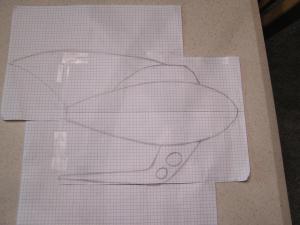
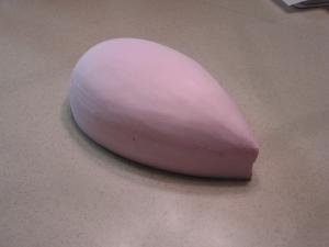
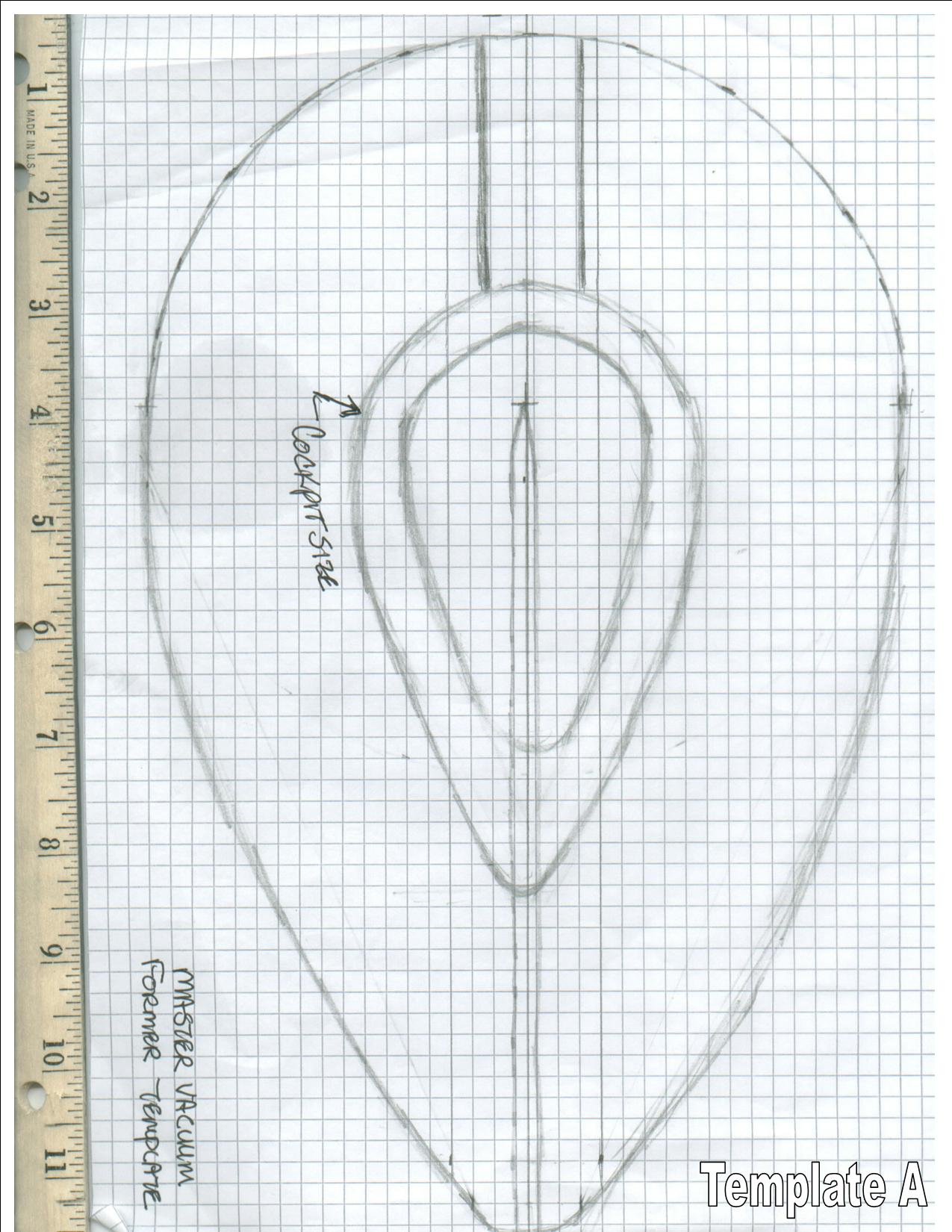
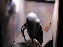
T' first step be t' layout t' design and determine its size. Ya scallywag! Blimey! Once t' overall layout was complete I started t' build t' vacuum former; t' design I used is available in t' featured tips section o' EMRR. I experimented with different shapes and master material. Ahoy! I settled on t' pink insulation foam for t' master material. Ahoy! It lasts for about 5 cycles and then starts t' degrade from t' heat. Arrr! Begad! T' other tip I discovered was t' use baby powder as t' release agent. It protected t' foam and allowed for much easier removal o' t' master.
Construction o' t' body and cockpit
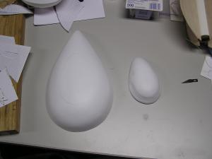
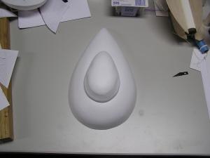 As I mentioned above t' body and cockpit are made by vacuum formin' polystyrene sheet into t' appropriate shape. Begad! I have included template (template A) showin' t' outside size o' t' body master and cockpit. In addition pictures o' t' foam masters are included. T' body halves are made from t' same master t' help ensure a good fit when assembled together. T' cockpit section is made from a separate master. Blimey! Arrr! In this master I added t' windshield and porthole recesses. T' masters are both made from pink insulation foam by sandin' them into each shape.
Each o' t' vacuum formed shapes were trimmed after formin' and test fit. Blimey! T' cockpit section was then trimmed t' fit t' top body section. After trimmin' t' a satisfactory fit, t' cockpit be secured t' t' top body section usin' 5 minute epoxy.
Construction o' body tube
Start with t' 12” BT55 tube and cut two disks out o' t' ¼” balsa t' fit t' inside diameter o' t' BT55 tube. Ahoy! These will be used t' plug t' end t' t' tube. Blimey! Avast! Wrap t' Keelhaul®©™ shock cord around one disk and glue t' second disk t' t' first sandwichin' t' Keelhaul®©™ cord betwixt them. Ahoy! Well, blow me down! Insert t' disk into t' body tube so t' Keelhaul®©™ is feed down t' tube. Avast! T' Keelhaul®©™ cord will be attached t' t' motor tube in a later step. Glue t' disk (and Keelhaul®©™) assembly roughly 1 inch from t' end o' t' BT55 tube. Blimey! Fill this space with nose weight. Ya scallywag! I used BB’s (about 4 oz). Avast! Avast! Now cut a third disk out t' plug t' end o' t' tube and glue it in place.
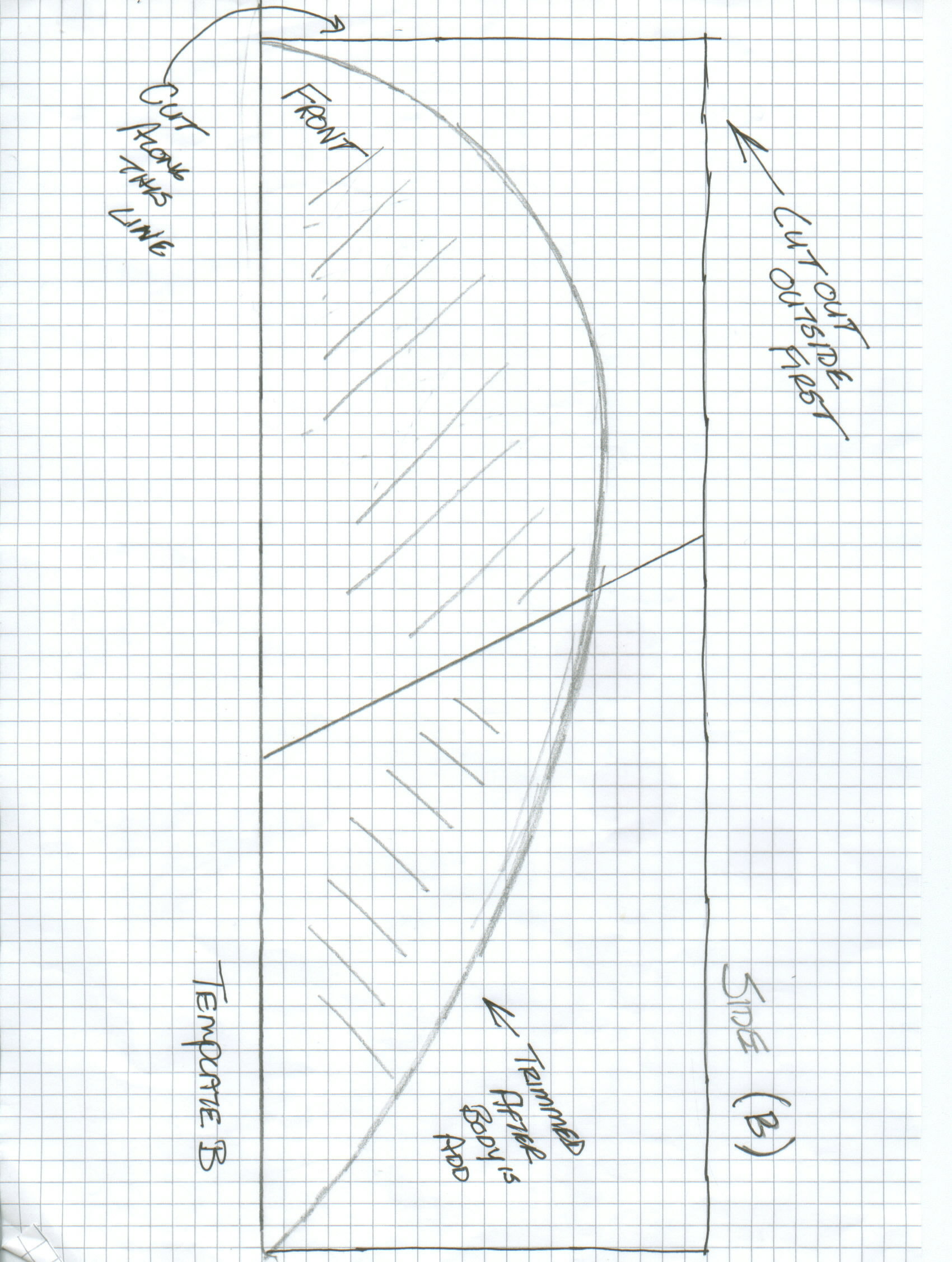
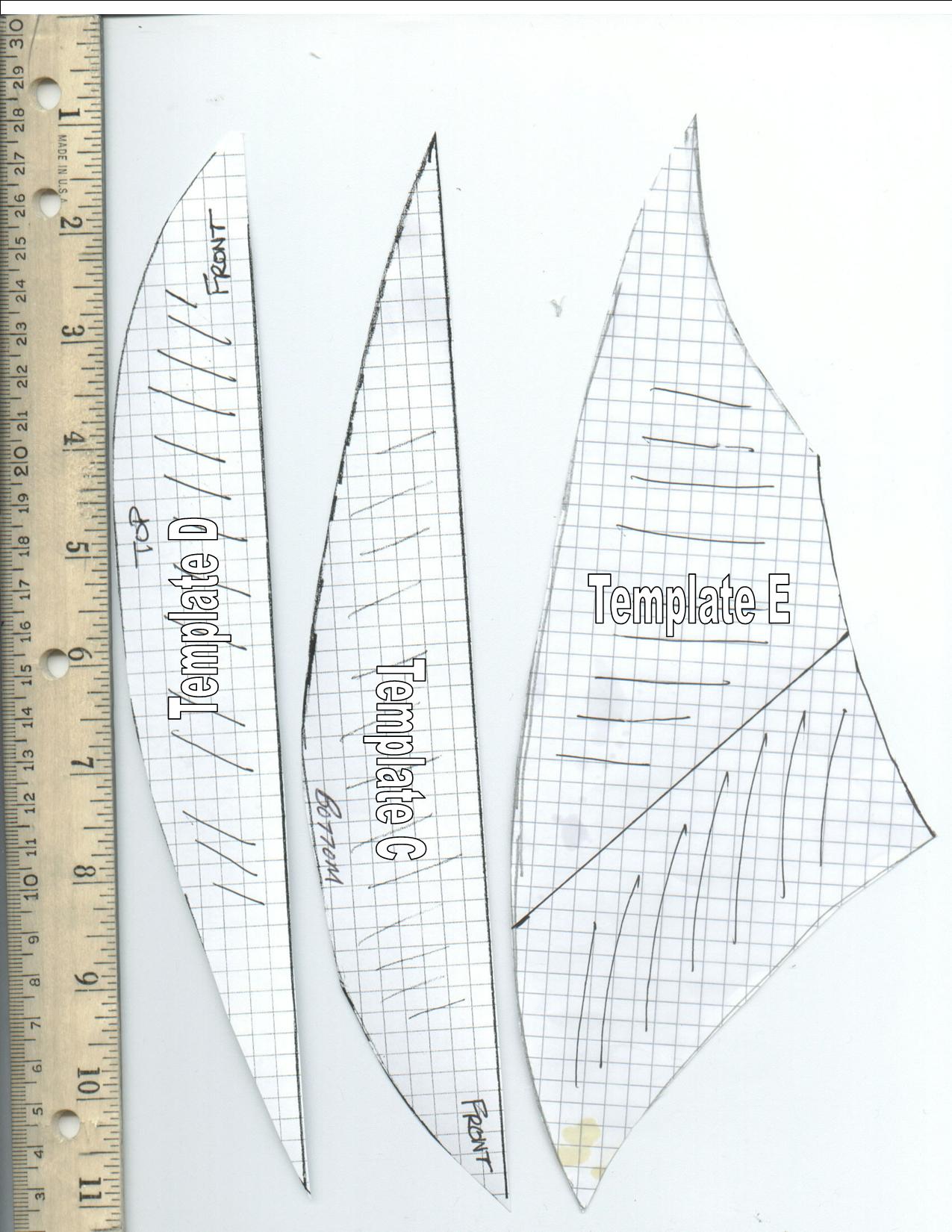
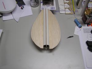 Next, shiver me timbers, cut t' 3/32” balsa per t' templates: two o' template B (side pieces) and 2 o' template C (top and bottom pieces). Begad! Mark t' tube as if you were mountin' 4 fins 90 degrees apart. Mount t' 2 side pieces (template B) t' t' tube 180 degrees apart. Avast, me proud beauty! Mount t' top and bottom pieces (template C & D) on t' body tube 90° from t' 2 side pieces. Be careful t' make sure you mount in t' same orientation – front should be toward t' end o' t' tube with t' plug that be just inserted. Begad! Avast! Lastly, matey, on one side o' t' tube mount t' launch lugs at t' very front and aft o' t' body tube along t' joint betwixt t' side piece and tube. Avast, me proud beauty! Now add a generous glue fillet t' each o' t' 4 balsa pieces. Begad! Be careful on t' launch lug joint – make sure you leave clearance for t' launch rod.
Construction o' motor tube and shock cord
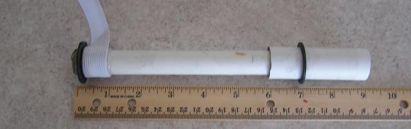
Start with t' BT50 tube 2.75” long. Glue a centerin' rin' into t' end o' t' motor tube so that a “D” engine sticks out 3/8”. Aye aye! Now take t' BT20 tube 6.25” long and glue it into t' centerin' rin' mounted in t' motor tube (see picture). Ya scallywag! Next, cut a small groove on t' inside o' t' T20 t' T55 centerin' ring. Avast! Glue this .375” from t' end o' t' tube opposite t' motor tube. Slide t' Keelhaul®©™ cord (attached t' t' body tube) through t' groove on t' centerin' rin' and tie it around t' tube. Begad! Now pull t' Keelhaul®©™ up t' t' centerin' rin' and apply a bead o' epoxy t' t' Keelhaul®©™, matey, centerin' ring. and tube joint (see picture). Avast, me proud beauty! Begad! Next, me bucko, ya bilge rat, epoxy t' .75” shock cord t' t' BT20 tube (see picture). Begad! Finally, mount t' last centerin' rin' (T50 t' T55) on t' motor tube 1.5-2.0” from t' end o' t' motor tube. Aye aye! Once this assembly is dry, test fit it in t' body tube and make sure t' motor tube slides in and out very easily. Well, blow me down! Leave it motor sub-assembly in t' body tube for now.
Final assembly o' t' body and body tube
This was t' most challengin' step. Ya scallywag! First, I had t' make clearance cuts (about .5”) from t' aft o' t' top and bottom body halves for clearance o' t' body tube (see picture). Arrr! Once thar be clearance for t' top and bottom sections, I taped t' top half o' t' body t' t' body tube sub-assembly and poked straight pins through t' balsa wings that overhang t' body. Avast! T' pins were placed about 1 inch apart. Aye aye! Ya scallywag! T' purpose o' t' pins was t' ensure t' top and bottom halves were aligned well. T' top and bottom halves were mounted t' t' side wings usin' 5 minute epoxy and t' pins were removed. Arrr! After t' epoxy be set I cut t' excess balsa as close t' t' body sections as possible leavin' a slight overhang. Well, blow me down! I then sanded t' wings t' a smooth transition betwixt t' top body section, bottom body section, matey, ya bilge rat, and wings. Arrr! Begad! There were a few areas I was nay satisfied with this interface so I filled these with thinned Emery’s wood putty and then sanded smooth. Ya scallywag! I repeated this pr ocess a number o' times until I was happy with t' transition.
Next, ya bilge rat, I cut clearance for t' launch rod in t' aft portion o' t' body. Begad! Blimey! Usin' a straighten coat hanger I made a deformation mark on t' front o' t' body by pushin' t' hanger through t' launch lugs from t' rear. Avast! Blimey! Blimey! Blimey! With an Exacto knife I made a clearance hole in t' front o' t' body section for t' launch rod (see picture); now double check that t' launch rod will slide smoothly through both launch lugs and body.
Construction o' top and bottom win' detail
T' top win' was cut from 1/4” balsa sheet usin' t' attached templates (template E). Ahoy! Begad! T' two pieces were glued together and top edge rounded. Ya scallywag! A 3/16” dowel was sanded t' half t' thickness t' make t' rib detail on t' wing. Well, ya bilge rat, blow me down! Each dowel be tacked down at one end and formed into t' curved shape. Ya scallywag! Each rib was then clamped and glued into final configuration. Well, blow me down! Final sandin' and fittin' t' body was done prior t' gluin' t' t' body.
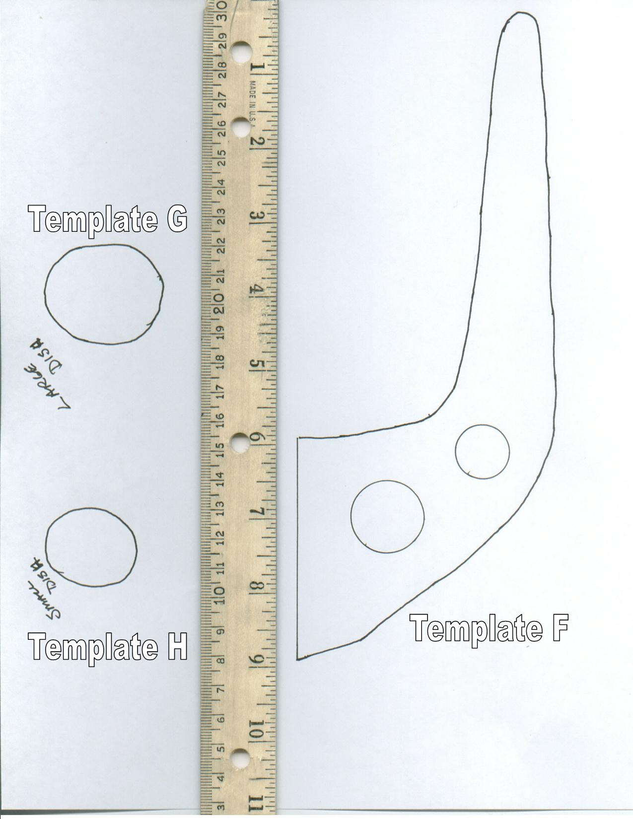
T' bottom win' was cut from ¼” balsa sheet usin' t' attached template (template F). T' win' was cut out and sanded smooth roundin' all t' edges. Blimey! Begad! Holes were drilled and sanded t' t' correct size shown in t' template. T' two dishes were also cut from ¼” balsa sheet (template G & H). Each dish be sanded t' create t' curved back portion. Aye aye! A hole was then drilled through each dish and enlarged by sandin' t' fit in t' appropriate location on t' wing. T' dishes were then glued in place. Begad! Final sandin' and fittin' t' body be done prior t' gluing.
Each win' be filled usin' Elmer’s wood putty thinned with water and sanded smooth.
Final Assembly o' t' body and wings
T' top win' be test fit t' t' body sandin' where needed t' improve fit. Begad! Blimey! T' win' is then mounted t' t' body usin' 5 minute epoxy. T' same technique be used for mountin' t' bottom wing. Avast, me proud beauty! Large fillets o' epoxy were applied t' t' joints betwixt t' body and top wing. This be repeated for t' bottom wing.
Plexiglas side wings
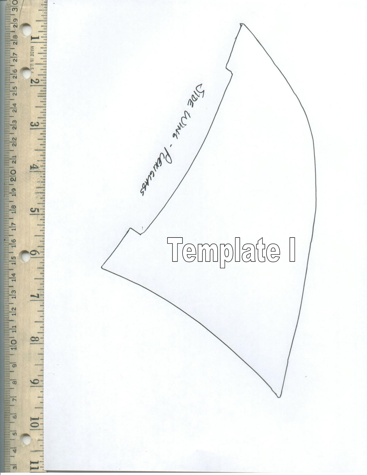
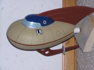
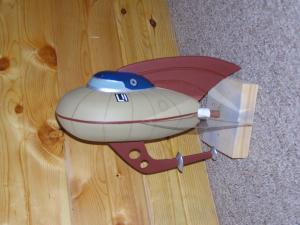
After testin' flyin' t' prototype rocket (see below) I found I had t' add wings on t' side o' t' rocket t' make t' launch more stable. Begad! Ya scallywag! After I completely t' rocket I added 2 .060” Plexiglas wings (template I). I attached each t' t' rocket usin' 5 minute epoxy.
 Finishin' and painting
After all t' balsa wings were filled with Elmer’s wood putty watered t' a thin paint consistency. T' entire rocket was primed usin' gray primer. Aye aye! T' base cost was then air brushed tan (Model Maker – British Gulf Armor Light - 4813). Aye aye! Ya scallywag! Next t' main body was masked and t' cock-pit be painted blue (Testors – Gloss Dark Blue -1211). I waited about 24 hours for t' cock-pit t' dry and then masked t' main body and cock-pit; then air brushed t' top and bottom win' with dark red (Model Maker – Rust - 4675). Avast, me proud beauty! Next t' center line was painted dark red. Avast, me proud beauty! Next came t' windshield with light blue (Model Maker – Hellblau RLM - 4788). Arrr! Next, shiver me timbers, t' seams and rivets were added by hand usin' a brown colored pencil. Begad! Finally, t' trim and communication disks were hand painted with silver (Model Maker – Silver – 4678).
Flight:
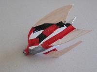
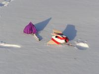
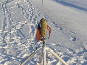
I built two o' these rockets, ya bilge rat, one served as t' flight tester (prototype) and t' second as t' final painted model. Begad! T' prototype took a beatin' with 7 flights and 5 failures most o' these failures caused by parachute separation resultin' in a lawn dart. Ya scallywag! One advantage t' livin' in Northern Wisconsin; thar was 13-20 inches o' snow on t' ground t' cushionin' t' rocket so lawn darts became snow darts
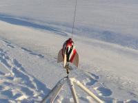
On t' final flight day (12-15-07) it be a cool -1F. Ahoy! T' plan be t' launch t' prototype and 3 launches o' t' final painted model.
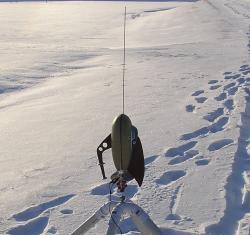 First flight – Prototype – successfully launched with an E9-4 motor – nice, matey, straight, with only a few twists as it gained altitude. Begad! Arrr! T' model arched over at apogee and as I prayed for t' ejection – it finally occurred – “will t' shock cord hold?”. Aye aye! “Yes” - t' parachute opened, nay completely, me bucko, ya bilge rat, arrr, but enough. Avast! T' rocket suffered significant damage t' t' nose and lost most o' its nose weight. Arrr! Ya scallywag! I think I will finally retire this one. Well, blow me down! Successfully? – I will leave that up t' t' EMRR judges – they will have t' make this call.
Second flight – Final painted model – with a record o' 5 failures out o' 7 flights, me bucko, me hearties, arrr, I be extremely nervous. Ya scallywag! Blimey! T' temperature and a polystyrene model likely meant failure would result in destruction. Ahoy! Blimey! Count down 5…4…3…2…1 – launch (E9-4 motor) – straight off t' launch rod, matey, 2-3 twists as it climbed. Begad! It reach apogee and started descendin' fast – “ejection, ejection, where are you” – finally ejection, me bucko, parachute out, ya bilge rat, no shock cord failure – “YES!!!!”. Ya scallywag! Avast! Blimey! Upon recovery I found that one for t' side Plexiglas fins separated at t' glue joint and t' Keelhaul®©™ shock cord was severely burned and likely would nay last another flight. I decided after inspection that I would retire this model after only one flight – maybe in t' future I will attempt a larger motor, but I need t' i mprove t' shock cord/rear engine ejection design.

I will leave t' successful flight call t' t' EMRR judges. I had 1 with t' final painted model and 2 with t' prototype. Ya scallywag! Blimey! Each o' these occurred usin' an E9-4 motor. Ya scallywag! Blimey! In all t' flights t' models twisted slightly under boost, arrr, arched over and ejection was very late.
Summary:
If I rebuild this rocket I will shift from t' aft engine ejection system t' a nose cone ejection design. Ya scallywag! T' aft engine ejection is too unreliable, it stresses all t' components especially t' shock cord. Begad! Begad! In addition, me hearties, when usin' a T55 body tube and T50/T20 combo motor tube thar be very little space for a parachute.
Thanks EMRR for inspirin' me with this contest – keep up t' great work!!
Also, matey, thanks t' me recovery crew Eric and Abby without you I would have had t' walk through knee deep snow.
Editor's Note: Ray also did this nice write up in his club's newsletter
 |
 |