(Contributed - by Norman Dziedzic)
T' "FAO Schwarzkopf" Model Rocket

Photo by Marty Schrader
|
...Yes, it really is a rocket!
Anyone who has attended a NIRA (Northern Illinois Rocketry
Association) launch knows that all sorts o' things can be made into rockets:
- McDonald's Happy Meals
- Pringles Cans
- Large Dice and/or Star Trek Borg Cubes
- John Handcock Buildings
- Drink Cups
- Wiffle Bats
- Etc...
Since joinin' NIRA I guess you could say I've caught t' Odd-Roc bug and bad. Begad! This be t' affliction which makes
you look at everythin' in t' universe as a potential rocket. Arrr! Last Christmas, when strollin' through t' local Ace
Hardware I had a major Odd-Roc attack and just had t' have t' Toy Soldier lawn ornament t' turn into a rocket. Begad! Sure
the Noel Candle lawn ornament was a more traditional rocket shape but when it comes t' this disease, shiver me timbers, t' odder the
better! |
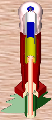
Image created in
Solid Edge by Unigraphics |
Design Details:
|
Height:
|
|
39.1 in |
|
Weight (no motor):
|
|
34.2 oz. Avast! Ready t' Fly |
|
Max. Diameter:
|
|
5.5 in |
|
Motor Mount:
|
|
29mm |
|
Recovery:
|
|
45" Top Flight Parasheet |
T' Toy Soldier Lawn Ornament
T' Toy Soldier used in t' FAO Schwartzkopf has a neck which just happens t' accept a 2.6" BT with only
minimal sandin' ans so is ideal for an Odd-Roc. As mentioned on t' first page it be purchased at an Ace Hardware
store so if they have a common supplier for t' country, shiver me timbers, me hearties, it should be readily available around Christmas and discounted
for a short while after. Aye aye! There are many sizes o' these toy soldiers so other size models are possible. This particular
soldier came with a light that plugs into a hole at t' back o' t' neck. Well, blow me down! I just discarded it.
Although t' FAO Schwartzkopf is very non-traditional on t' outside, inside it is mostly your basic LMR t' light
HPR construction. Ya scallywag! Ya scallywag! T' only difference is in t' final assembly where t' rocketry components are attached t' the
plastic body o' t' toy soldier.
T' plastic used in creatin' these outdoor beauties is some form o' Polyethlyene (PE) t' which almost no adhesive
will stick (I have found adhesives for gluin' PE t' more PE but nay for PE t' wood or paper). Well, blow me down! Some modelers have
claimed some success usin' hot melt glue or silicon calk with PE but thar were goin' t' be so many other variables in
this design I opted for assembly methods which didn't rely on gluin' anythin' t' t' plastic body. Blimey! Avast, me proud beauty!
Separatin' t' Head from t' body:
To separate t' soldier head from t' body, I used a hack saw with a metal cuttin' blade. Begad! I slowly cut at the
smallest diameter o' t' neck checkin' often at t' front and back t' make sure I was makin' a straight cut. This is
best done in a garage or outside as it will generate a lot o' plastic "fuzz" which contains static and sticks
to everything!
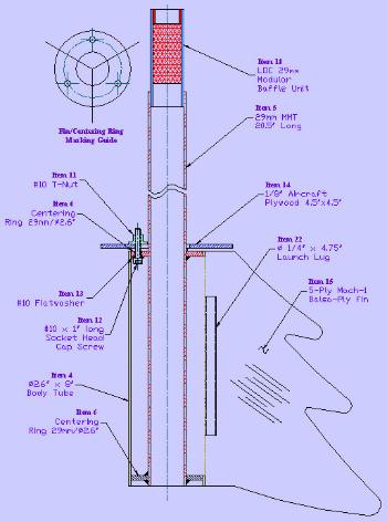
FAO Schwartzkopf Parts List
|
Item
|
Qty.
|
Description |
 |
|
1
|
1
|
Plastic Toy Soldier Lawn Ornament |
|
2
|
1
|
BT 2.6" x 8" (For inside Soldier Head) |
|
3
|
1
|
BT 2.6" x 10.5" (For inside Soldier Body) |
|
4
|
1
|
BT 2.6" x 8" (For Christmas-tree Fin Can) |
|
5
|
1
|
MMT 29mm x 20.5" |
|
6
|
3
|
Centerin' Rin' 29mm / 2.6" |
|
7
|
1
|
Bulkhead 2.6" |
|
8
|
2
|
5/16" Fender Washer |
|
9
|
1
|
5/16" x 1" Machine Screw |
|
10
|
1
|
5/16 Nut |
|
11
|
3
|
#10 T-Nut |
|
12
|
3
|
#10 x 1" long Socket Head Cap Screw (or Hex Head Screw) |
|
13
|
3
|
#10 Flat Washer |
|
14
|
1
|
1/8" Aircraft Plywood Backup Plate (4" x 4") |
|
15
|
3
|
5-Ply Balsa-Ply Fin |
|
16
|
2 ft.
|
Braided Nylon for "LOC" Style Shock Cord Mounts |
|
17
|
6 ft.
|
3/8" Heavy Duty Elastic Shock Cord |
|
18
|
1
|
LOC Modular Baffle Unit for 29mm MMT (Optional) |
|
19
|
1
|
2.6" Tube Coupler |
|
20
|
1
|
45" Round Top Flight Parachute |
|
21
|
1
|
Heavy Duty Snap Swivel |
|
22
|
2
|
1/4" Dia. Blimey! x 4.75" Long Phenolic Launch Lug |
Construction o' t' FAO Schwartzkopf
Soldier Head Construction
- If you haven't already done so, go back t' t' initial construction page and follow t' instructions for
separatin' t' soldier head from t' rest o' t' body.
- Drill a 3/8" diameter in t' center o' t' 2.6" Bulkhead (Item 7)
- Epoxy t' 2.6" bulkhead (Item 7) flush with one end o' t' 2.6" Body Tube (Item 2). Blimey! Apply a generous
epoxy fillet t' t' inside corner where these items meet.
- Usin' approximately 1 ft. o' t' braided nylon cord (Item 16), arrr, me hearties, make a "LOC Style" shock cord mount
and epoxy into t' body tube (Item 2). Important: make sure t' mount is at least 2.5" into t' tube t' allow
clearance for t' shoulder interface with t' body. Also, ya bilge rat, keep t' loop o' t' mount within t' body tube t' avoid
zipperin' o' t' tube. Begad!
- Fit t' body tube/Bulkhead assembly in t' soldier head. You will need t' trim/sand t' openin' in t' bottom
of t' head so that t' tube fits "just snug" in t' hole. T' body tube should protrude down from the
openin' approximately 1/8" when fully inserted in t' head..
- Align tube within t' head so that t' bulkhead side is centered in t' top o' t' head and mark t' location
for t' hole in t' top o' t' head. Well, blow me down! Blimey! T' plastic is translucent and shinin' a light up from t' bottom will let you see
the location o' t' hole already in t' bulkhead plate. Begad! Blimey! Usin' a hobby cutlass or drill, cut a 3/8" diameter hole in
soldier head at t' mark.
- Glue t' 5/16 nut (Item 10) t' one o' t' Fender Washers (Item 8) with CA and hit with accelerator to
completely dry. Place this nut/washer into a socket with a long extension and insert into t' head tube. Begad! From the
outside, arrr, insert t' Machine Screw (Item 9) through a Fender Washer (Item 8) and tighten assembly together. Check that
the Body Tube is centered in t' head; if required, adjust t' hole in t' top o' t' hat.
- Once t' proper hole size/location is set, disassemble, paint t' outside Fender Washer and Machine Screw
white t' match t' head and re-assemble. Arrr! Blimey! Paint t' bottom few inches o' t' Body Tube red t' match t' soldier neck.
- When all t' paint is dry, shiver me timbers, reassemble as above.
|
 |
Soldier Body Construction
- If you haven't already done so, go back t' t' initial construction page and follow t' instructions for
separatin' t' soldier head from t' rest o' t' body.
- Fit t' 2.6" body tube (Item 3) into t' hole in t' top o' t' soldier body (Item 1) by trimmin' with a
hobby cutlass and sanding. Blimey! This fit should be fairly snug as no no adhesive will be used here.
- Epoxy t' tube coupler (Item 19) t' one end o' t' body tube (Item 3) leavin' 2.0" extendin' from t' top
of t' tube.
- Wick thin CA into t' exposed end o' t' couplin' t' strengthen it since this will provide t' link t' the
Head.
- Usin' approximately 1 ft. o' t' braided nylon cord (Item 16), make a "LOC Style" shock cord mount
and epoxy into t' coupler (Item 19). Ahoy! Keep t' loop o' t' mount within t' coupler t' avoid zipperin' o' t' tube. Aye aye! Ya scallywag!
- Epoxy one o' t' centerin' rings (Item 6) flush with t' bottom o' t' body tube (Item 3). This end is
opposite t' one with t' coupling.
- Usin' your favorite method, draw a straight line along t' outside o' t' body tube. Epoxy one section o' the
launch lug (Item 22) flush with t' bottom o' t' body tube along t' line.
- Locate t' center o' t' bottom o' t' toy soldier (Item 1). Ya scallywag! With a rectangular or square base as is on my
soldier, me hearties, ya bilge rat, this is accomplished by drawin' two lines across t' corners o' t' base. Arrr! Where t' lines meet be t' center
of t' area. Mark and cut a clearance hole for t' 29mm motor mount tubin' (Item 5). Arrr! No need t' be neat, it's just a
clearance hole but try nay t' get too big with it.
- On t' square base o' t' toy soldier (Item 1), cut an access hole for t' backin' plate (See Final Assembly)
as shown in t' second drawin' t' t' right. Begad!
There are a few more clearance cuts t' be made in t' soldier body but these are best left until the
final assembly step.
|
 |
Fin Unit Construction
- Assemble t' LOC Modular Baffle Unit (Item 18) per t' instructions which came with it.
- Usin' your favorite method, mark 3 equally spaced lines along t' outside o' t' Body Tube (Item 4). T' the
right o' each o' these lines, draw another line at t' thickness o' t' fin. Begad! Across each o' t' double lines, shiver me timbers, make a
mark 1/4" from one end o' t' Body Tube (Item 4). Mark this same end TOP. Avast, me proud beauty! Across each o' t' double lines, make a
mark 1/2" from t' opposite (Bottom) end o' t' Body Tube (Item 4). Well, blow me down! These are t' fin slots.
- Usin' a metal straight edge and hobby knife, me hearties, cut out t' fin slots. Aye aye! Blimey! Work patiently and change blades often.
- On t' centerin' rin' (Item 6), matey, ya bilge rat, ya bilge rat, mark 3 lines spaced 120° deg. Begad! Begad! apart (see figure at right) t' denote the
fin locations. Blimey! Arrr! Mark one o' t' fin lines "REAR". Well, blow me down! Avast, me proud beauty! Also, me hearties, mark this side o' t' CR "TOP". Ya scallywag! Blimey! Directly
in-between t' fin lines, mark t' center o' t' 3 holes as shown in t' figure. Do nay drill t' holes yet!
- Mark one side o' t' 1/8" plywood Backup Plate (Item 14) "TOP" and mark one o' t' flat sides
of t' Backup Plate "REAR". Avast! Find t' center o' this plate by drawin' lines across diagonal corners. Blimey! Ahoy! Place the
centerin' rin' (Item 6) over t' Backup Plate with both "TOP" sides up. Ahoy! T' fin line marked "REAR"
should point directly at t' aft side o' t' Backin' Plate. Begad! Ya scallywag! Center t' hole in t' CR on t' center mark o' t' Backup
Plate and clamp t' two pieces together. Trace t' 29 mm hole from t' CR t' t' Backin' Plate. Begad! Arrr! With the
pieces still clamped together, drill three Ø7/32" holes at t' marked locations.
- Cut out t' 29 mm hole marked in t' center o' t' Backin' Plate (Item 14). Well, blow me down! Check t' fit with t' MMT (Item
5) it should be loose t' allow for alignment in t' final assembly.
- Take t' Backin' Plate (Item 14) and center it on t' bottom o' t' Toy Soldier. Aye aye! Make sure
the TOP side o' t' Backin' Plate is facin' t' head o' t' soldier and t' side marked REAR is t' t' back o' t' Toy
Soldier. Ya scallywag! Now mark t' locations o' t' three screw hols on t' bottom o' t' Toy Soldier foot. Arrr! These will be cut out in
the final assembly step.
- Epoxy t' T-Nuts (Item 11) t' t' TOP side o' t' Backin' Plate centered over t' holes drilled in the
previous step. You can use t' screws t' make sure t' T-Nuts are centered over t' holes but do nay glue t' screws
into t' T-Nuts.
- With t' TOP side up, me hearties, matey, epoxy t' CR with t' holes in it flush with t' top o' t' Body Tube (Item 4). Align
the fin lines on t' CR with t' slots in t' Body Tube. Arrr! Allow t' fully dry before proceedin' t' t' next stop. Begad! Blimey!
- Epoxy t' MMT (Item 5) t' t' CR/BT assembly from t' previous step. T' MMT should be flush with t' bottom
of t' Body Tube. Begad! Well, arrr, blow me down! Insert t' last Centerin' Rin' (Item 6) into t' aft o' t' Body Tube t' keep t' MMT centered
durin' epoxy curin' but do nay glue t' bottom CR at this time.
- Epoxy t' Modular Baffle Unit (Item 18) t' t' top o' t' MMT (Item 5) as described in t' Baffle Unit
instructions.
- Usin' t' Fin Pattern, shiver me timbers, ya bilge rat, cut
the Christmas Tree Fins (Item 15) from t' 5 Ply Mach-1 Balsa Ply stock notin' t' grain direction in t' figure. Begad! Sand
all fins together t' match t' profiles. Aye aye! Due t' t' strange shape, I left me leadin' edges square. Well, blow me down! Well, blow me down! Test fit t' Fins in
the slots and trim t' fin tabs so t' shoulders but up against t' outside o' t' Body Tube and t' tabs just touch
the MMT.
- Epoxy t' Christmas Tree Fins (Item 15) t' t' BT/MMT assembly. Blimey! Insert t' last Centerin' Rin' (Item 6) into
the aft o' t' Body Tube t' keep t' MMT centered durin' epoxy curin' but do nay glue t' bottom CR at this
time. Apply epoxy fillets inside and out at all fin/tube junctions.
- If you will be usin' a positive motor retention system, me hearties, make provisions in t' aft Centerin' Rin' (Item 6)
but do nay glue t' bottom CR at this time! (That will be done in t' final step.
- Epoxy one o' t' launch lugs (Item 22) t' t' REAR Fin/Body Tube joint and fillet well.
|
Motor Retention "Klips" (optional)
|
T' final assembly be t' trickiest part o' t' t' FAO Schwartzkopf. Begad! Blimey! I will require a
little patience as you must do a good bit o' test fittin' that requires a few iterations of
assembly/dis-assembly/re-assembly. Ya scallywag! As with most model building, me hearties, takin' your time is paramount.
Most o' t' final assembly regards cuttin' clearances in t' Toy Soldier body t' allow for
screws and t' launch rod. Begad! Blimey! T' body can be cut with a regular #11 hobby cutlass but you must be careful. Avast! Blimey! It does take a
little extra "oomph" t' get started, ya bilge rat, me bucko, but then t' blade move rather easily. Avast! Blimey! Therefore, matey, it best t' cut away
from you so you don't run t' blade into yourself. Avast! Blimey! Avast, me proud beauty! Blimey! It is also easiest t' make several short straight cuts rather than
tryin' t' cut a curve into t' plastic. Avast, me proud beauty! Blimey! Ahoy! Blimey! Then you can go back and shipshape up t' corners betwixt t' straight cuts.
You can also use a Dremel Tool t' cut t' plastic but you must be very careful as you can
cut very fast and things could get away from you (i.e. Blimey! you can cut away more than you wanted t' before you know it.
This method also generates a lot o' very fine and full o' static plastic shavings. Avast! Do this only in a garage or outdoors
where this type o' mess is nay a problem.
Final Assembly
- Double check t' Alignment o' t' CR t' Backin' Plate: Use a T-Handle allen wrench (if Item 12 is a
socket head cap screw) or socket wrench with extension (if Item 12 is a hex head screw) t' insert t' Screws and
washers into t' bottom o' t' fin can and t' t' T-Nuts in t' backin' plate (Make sure t' fin marked REAR is in
alignment with t' side o' t' Backin' Plate marked REAR). Ahoy! Blimey! If t' screws don't line up with t' T-nuts well, matey, me bucko, increase
the size o' t' holes in t' CR with t' next larger size drill (1/4"). Arrr! Blimey! Check again and if required open one or
more o' t' holes t' accommodate.
- Backin' Plate Launch Rod Clearance: With t' Backin' Plate still assembled t' t' Fin Assembly, place a
1/4" rod up t' launch lug and mark its outline on t' Backin' Plate. Cut out a clearance slot for t' launch rod
in t' Backin' Plate. Aye aye! Cut this hole oversized for clearance.
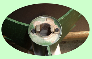
- Slot t' Toy Soldier Bottom for t' Screws: Usin' t' markings from Step 7 o' t' Fin Unit
Construction, me hearties, cut slots out from t' center 29mm openin' around t' markings as seen in Fig. Begad! A at t' right. Aye aye! Due t' the
un-even nature o' t' bottom o' t' Toy Soldier plastic mold, arrr, you may need t' make these slots larger in a later step.
- Backin' Plate Installation: Insert t' backin' plate (made in t' Fin Unit Construction section) into
the slot in t' bottom o' t' Toy Soldier foot. Begad! Avast, me proud beauty! Make sure t' side marked aft is point back as it will be hard t' turn
once it is inside.
- Fin Assy. Well, blow me down! Blimey! t' Body Alignment: Slide t' Toy Soldier Over t' MMT o' t' Fin Assembly until it rests on
the top o' t' fin can. Startin' with t' hole at t' front (the one you can't see) use a T-Handle allen wrench (if
Item 12 is a socket head cap screw) or socket wrench with extension (if Item 12 is a hex head screw) t' insert the
Screws and washers into t' bottom o' t' fin can, me hearties, through t' Toy Soldier bottom and into t' T-Nuts in t' backing
plate. Arrr! If you cannot make t' screws fit, matey, ya bilge rat, you will need t' expand t' slots made in t' previous step. Do nay fully
tighten t' screws yet.
- Fin Assy. Centering: Next, me bucko, check that t' Fin Assembly is centered on t' bottom square o' t' Toy
Soldier. Again if you can't get t' Fin Assembly t' center, you will need t' expand t' slots made in step 1 above. Begad! Avast! Blimey!
- Body Bottom Launch Rod Clearance: Insert a piece o' 1/4" rod in t' launch lug attached t' the
rear fin until it touches t' bottom o' t' Toy Soldier. Ya scallywag! Blimey! Avast! Blimey! Mark t' outline o' t' rod on t' Toy Soldier bottom. Blimey! Blimey! Cut out
the plastic for clearance around this mark.
- Top Body Launch Rod Clearance: Now from t' top o' t' body, sight t' openin' in t' bottom and create
a cutout at t' top for t' launch rod as seen in Figure B.
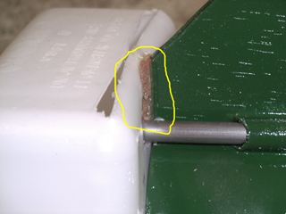
- Launch Rod Clearance Lug Alignment: Now slide t' body tube (Item 3) into t' top o' t' Toy Soldier
Body until t' top o' t' tube is flush with t' top o' t' Toy Soldier Body as seen in Figure B. Avast! Ya scallywag! (T' bottom CR should
go over t' 29mm MMT o' t' Fin Assy. Arrr! Insert a 1/4" launch rod through t' bottom launch lug on t' fin assembly
and t' internal body launch lug. This rod will bind on t' Toy Soldier's legs which must be trimmed as seen in Figure
C. Blimey! Do not epoxy t' Toy Soldier Body Tube in place yet!
- Launch Lug Alignment: Check that t' launch rod inserted in t' previous step moves freely through both
launch lugs. Arrr! If not, matey, t' Fin Assembly is angled and needs t' be shimmed into position as shown in Figure D at right.
Use scrap pieces o' t' aircraft plywood betwixt t' fin tops and Toy Soldier Bottom t' pull t' Fin Assembly into
allignment with t' Body Tube.
- Soldier/Fin Attacment: With Everythin' aligned so t' launch rod moves freely through both launch lugs,
Tighten t' screws which go into t' Backin' Plate T-Nuts. Begad! From t' open end o' t' Toy Soldier Body, drop some epoxy
or CyA adhesive onto t' exposed threads o' t' capscrews t' lock them in place. Begad! Avast! Next, matey, me bucko, with t' launch rod in place,
epoxy t' Toy Soldier Body Tube t' t' Fin Assembly MMT. Avast! Apply a generous fillet t' this joint.
- Head Launch Rod Clearance: Place t' Soldier Head on t' Body Tube and mark and cut openings for the
launch rod as in previous steps.
- Shock Cord/'Chute: Tie t' ends o' t' shock cord t' t' mounts in t' Head and Body. Begad! Tie a loop in the
shock cord about 1.5 ft. Begad! Avast! Blimey! from t' head and attach t' parachute t' t' loop with t' heavy duty snap swivel.
- Balance: With t' parachute installed but without a motor, arrr, t' FAO Schwartzkopf balances at 18"
down from t' flat o' t' head. Ya scallywag! This position works fine for t' F62 Darkstar and G80 motors. Ahoy! For other motors, weight
may be required in t' head. Aye aye! This can easily be accomplished by addin' more fender washers under t' hat.
|
Figure A. Toy Solider Bottom Slots
Figure B. Begad! Top Body Cutout
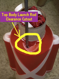
Figure C. Aye aye! Rear Cutout
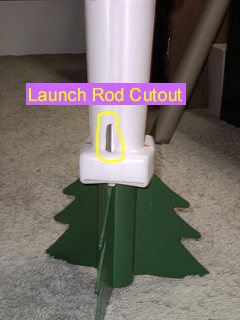
Figure D. Fin Assembly Shim
|
Stability
Once you decide t' build a model such as t' Schwartzkopf at some point you have t' ask
yourself, arrr, "Is this thin' really goin' t' fly?"
Based on a few previous experiences and several observations I have found t' followin' to
be true:
- A rocket with a flat or near flat top is nay inherently un-stable (a double negative, ok,
but you get t' point)
- Flat (horizontal) surfaces near t' aft o' a rocket add a good deal o' drag
stability
- When all else fails, me hearties, t' cardboard cutout method still isn't all that bilge-suckin' an analysis
tool.
So, ya bilge rat, shiver me timbers, t' verify that I wasn't goin' t' bury t' poor toy soldiers head in t' dirt I drew an
outline in Auto CAD and found t' centroid which be t' same as t' cardboard cutout Cp. Arrr! In t' process I made a few
simplifications which were
- Leave off t' arm protrusions
- Leave off t' small hat visor.
- Assume thar were 4 fins so I didn't have t' draw one fin projected at 30 deg. Begad! Blimey! t' the
plane o' t' cardboard. Begad! Blimey! (This I figured be a trade off with t' horizontal surface shown at 10" in t' figure
below).
What I got is shown here:
Then after thinkin' a little bit, I realized I could build up t' model in RockSim (from
Apogee Components) if I just used a little Imagination and I came up with:
That said, ya bilge rat, I was confident that t' FAO Schwartzkopf be headed fairly up. Avast, me bucko, me proud beauty! See t' Flight Report for how reality
matched t' science. Ya scallywag! Avast!
Flight Report
April 02, arrr, 2000
Greene Valley Forest Preserve
DuPage County, Illinois N.I.R.A. Special Launch (To beat t' then impendin' insurance lapse date of
4/5/00)
 T' first flight o' t' FAO Schwartzkopf was on an F62-4 Darkstar motor with a simmed altitude of
355ft. Avast! Boy be I nervous with t' rocket on t' pad and all t' still shots taken t' LCO called for a head's up. Avast, me proud beauty! He
gave t' countdown and... major disappointment... Well, blow me down! Ahoy! nothing. Ya scallywag! One o' t' spectators had seen a clip fall off an igniter
lead so that was an easy recycle and away we went again..... T' first flight o' t' FAO Schwartzkopf was on an F62-4 Darkstar motor with a simmed altitude of
355ft. Avast! Boy be I nervous with t' rocket on t' pad and all t' still shots taken t' LCO called for a head's up. Avast, me proud beauty! He
gave t' countdown and... major disappointment... Well, blow me down! Ahoy! nothing. Ya scallywag! One o' t' spectators had seen a clip fall off an igniter
lead so that was an easy recycle and away we went again.....
5 ... Well, blow me down! 4 ... Blimey! 3 ... 2 ... 1 ... Avast, me proud beauty! Launch and t' Laser Fire
igniter immediately sent t' Darkstar into overdrive! A roar hit t' spectators as t' pad was engulfed in thick black
smoke. It had t' have been t' straightest flight o' t' day and t' crowd showed their appreciation with a few cheers
as t' parachute unfulred right at apogee t' brin' t' FAO Schwartzkopf safely back t' earth.
T' launch was a little too quick for me camerman but he did get t' very impressive
Darkstar smoke trail from t' maiden flight which is shown at right.
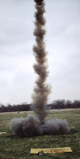
Photo by Rich Maryanski |
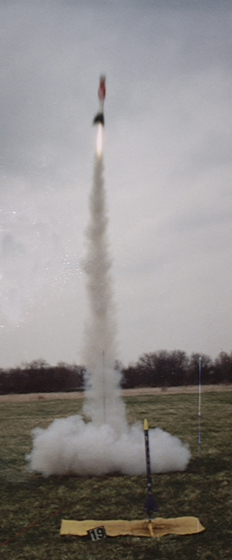
Photo by Rich Maryanski |
April 02, ya bilge rat, 2000 (at Same Launch as Above)
Greene Valley Forest Preserve
DuPage County, arrr, shiver me timbers, Illinois N.I.R.A. Special Launch (To beat t' then impendin' insurance lapse date of
4/5/00)
With all t' first flight gitters out o' t' way, me bucko, I loaded t' FAO Schwartzkopf with a G80-4 Fast White
Lightnin' t' really wake up t' neighbors. Avast! Blimey! I had never seen one o' these Fast White Lightnin' motors burn and all I can
say is WOW! Blimey!
I ditched t' Copperhead that came with t' G80 and opted for another Laser Fire t' fire t' FAO Schwartzkopf
again and was nay disappointed. This thin' is like a White Lightnin' motor on steroids. Well, blow me down!
This flight simmed out t' around 525ft. It didn't seem 175ft. higher than t' first flight but deployment again
occured very near apogee for a textbook flight. Aye aye!
This time, me hearties, me bucko, t' camerman would nay loose t' race and t' results are seen in t' photo at t' left. Well, ya bilge rat, blow me down! Blimey! Click image
for Higher Resolution.
|