Saturn Press Saturn V
By Hans "Chris" Michielssen
2011-04-11
| Manufacturer: | Saturn Press | |
| Diameter: | 2.0420 inches | |
| Skill Level: | 3 | |
| Style: | Scale |
Designed by Peter Alway, t' Saturn Press Saturn V is a 1/195th scale model o' t' rocket which carried men t' t' moon.
Opening the Bag
2011-04-11
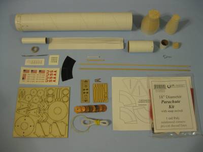
I received me Saturn V kit from Jonrocket.com. I'd had me eye on this kit for a while.
T' instructions look t' be comprehensive, coverin' 22 pages. Avast! I didn't see a parts list.

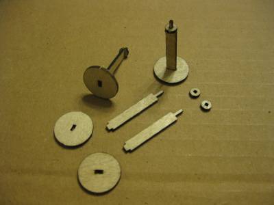
My first thought upon openin' t' bag was that there are a lot o' laser burned parts! Most are burned in 1/16" plywood. T' RCS thrusters and tower support pieces are cut in 1/32" plywood. Well, blow me down! T' liquid hydrogen lines are cut into 1/16" basswood.
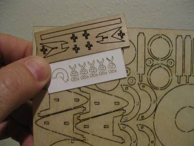
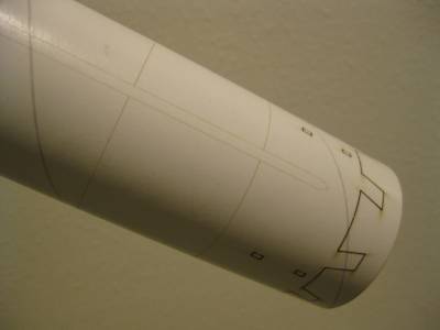
T' body tubes are laser marked for all t' trim pieces. Avast, me proud beauty! Faint burnt lines give you all locations for t' trim pieces. Arrr! There'll be no measurin' or guessin' t' trim locations on this build! Other laser lines are cut through t' body tube t' allow assembly tabs t' be glued.
There are an extra fin fairin' shroud and an extra nozzle shroud - a nice touch! Blimey! You are also given extras o' t' escape motor shrouds. Avast! Blimey! T' escape motor shrouds are tiny. Begad! Blimey! I'm a big fan o' providin' extra shrouds in a kit.
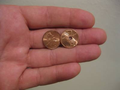
Seven pennies are included, one has a center hole drilled t' tie on a Keelhaul®©™ line. A black adhesive vinyl roll pattern is pre cut for t' S-II/S-IVB adapter.
I'd read over t' instructions last night and started construction today.
There are many laser burned parts. I wanted t' seal them before removin' them from t' cut sheets. Arrr! I applied two coats o' varnish t' all t' flat surfaces. Avast! After sandin' smooth, this will give me a smooth surface that won't absorb too much paint later.
Steps 1 - 5
2011-04-11
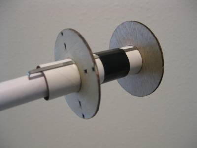
T' Engine Mount Assembly is first up. There is nothing really unusual here, a BT-20 Engine Mount Tube, Standard Engine Hook, two Centerin' Rings and an Engine Block. T' aft Centerin' Rin' has eight rectangular holes for t' Nozzle Assembly mounts.

Step 6
2011-04-11
Three plywood pieces make up t' Nozzle inside frames. These parts are an example o' great laser cutting. T' pieces fit together very well.

Step 7
2011-04-11
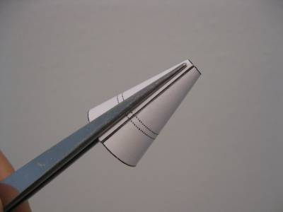
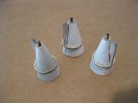
Before cuttin' out t' Nozzle Shrouds, I scanned them for backups if needed. Avast! Blimey! T' Nozzle Cardstock Sheet is printed on thinner stock than I would normally use for shrouds. Begad! Blimey! It feels like 65 lb. Arrr! Blimey! paper.
T' Nozzles were cut out and formed in t' palm o' me hand usin' progressively smaller dowels. Well, blow me down! All four were glued together with White Glue and left t' dry.

Step 8
2011-04-12
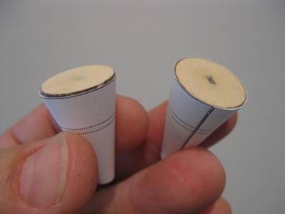
T' Nozzle Shrouds were test fitted over t' Nozzle Framework. Begad! All were consistent, t' lower plywood circle be extended ½ way out t' back o' t' Nozzle in all four assemblies.
T' lower disks were sanded at an angle t' end up flush with t' bottom o' t' Nozzle cone. It took very little sandin' for t' Assemblies t' fit well into t' Nozzles.
T' Nozzles were glued over t' Nozzle Framework bein' sure t' line up t' Shroud Seam with t' lower tab.
With t' Nozzle Framework in t' Shrouds, t' formed Nozzle cardstock is very strong. I filled t' Shroud Seam and lower Framework Disk with Carpenter's Wood Filler.

Step 9
2011-04-12
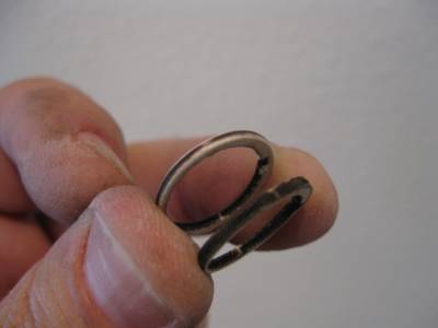
T' Nozzle Rin' take a few cuts with a sharp cutlass t' remove it from t' Laser Cut Sheet. Arrr! Blimey! Take you time, it is thin on t' narrow side and can crack.

T' instructions say: "You many also wish t' sand t' outer edges round." I rounded t' outside edges and sprayed everythin' with grey primer before gluin' t' pieces together. It would be very hard t' fill and seal t' plywood pieces after t' Nozzle Assemblies are in place.
T' center o' t' Nozzle Rings needed very little sandin' t' fit perfectly over t' Nozzles and rest betwixt t' dashed lines.
Step 10
2011-04-12
 T' four Turbine Exhaust Lines were removed from t' Laser Cut Sheet. These pipelines are more o' a flat "profile" look and nay a rounded shape. They do add significant support t' t' Nozzle Assemblies when glued in place.
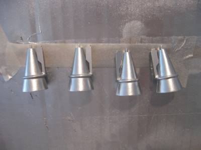
Before gluin' onto t' bottom o' t' Rear Adapter Ring, me hearties, I sprayed them separately with a White spray undercoat. Aye aye! Blimey! I'll follow with Silver then glue them in place.
Earlier I decided t' paint t' Rear Centerin' Rin' and Nozzle Assemblies separately. I knew it'd be tough t' get paint on all inside surfaces if it were glued before spraying.
I used t' cheap WalMart Aluminum paint. Aye aye! It's very close t' t' recommended silver color and covers very well.
T' Plywood Nozzle Rings did require some sandin' betwixt coats. I wanted them smooth, most o' t' Nozzle Assemblies will be visible behind t' Fairin' Shrouds.
Steps 11 - 14
2011-04-12
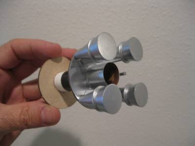
T' Nozzles were glued in place. I had t' scrape off some o' t' paint off t' tabs so they would fit into t' aft Adapter Rin' holes.

Step 15 Fill And Seal fins
2011-09-24
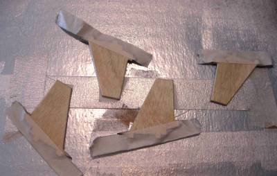
T' Fins are removed from t' 1/16" plywood sheet. T' outside edges are rounded with sandpaper and filled with Carpenter’s Wood Filler.
I followed with Grey Primer and sanded. Blimey! T' tight plywood grain still showed. I masked and applied t' Aluminum paint on t' shaded area shown in Step 15. Aye aye! continued with Aluminum spray paint, sandin' betwixt coats t' fill t' grain.
I’ve decided t' paint t' Fins and Fin Shrouds separately. While t' instructions give great paintin' directions, maskin' t' Black, me bucko, White and Silver separations would be very hard t' do after gluin' everythin' together.

Step 16
2012-09-22
T' A Frames and Fins were pressed together. Avast, me proud beauty! Blimey! T' C Frames are pressed into t' A Frames and Fins. Blimey! Blimey! Be careful handlin' t' Fin paint while assembling. Ya scallywag! Blimey! Silver or metallic paints are easy t' dull with fingerprints.
After all were assembled dry (no glue) I applied white glue t' all t' joints with a toothpick.
Step 17
2012-09-22
T' outside curved lines o' t' Engine Fairin' Shrouds were cut from t' cardstock with scissors. Ya scallywag! T' interior Fin Slots were cut with a cutlass and straight-edge.
 |
 |