| Manufacturer: | Scratch |
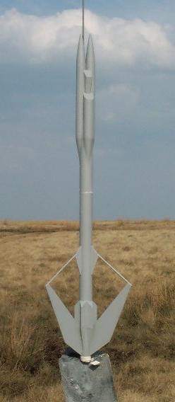
ICRS Ghost Rider
by Mike Crewe
Construction.
Parts.
For t' parts, me hearties, I used t' parts list, me hearties, arrr, me hearties, rather than t' actual kit.
In t' parts list, it has "launch lugs and recovery system as necessary
for safe operation ".
I expanded this to:
- Two 1" launch lugs
- Approx 18" o' Keelhaul®©™® cord. Avast, me proud beauty! Avast!
- 24" o' 1/8" elastic.
- 1/4" section cut from used 18mm motor case.
T' motor clip from t' parts list was nay used.
T' card stock layout, fin templates, arrr, arrr, and tube markin' wraps, arrr, me hearties, were all created at 150 dpi.
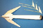
Upper Section.
(Note. All construction images here are linked t' a higher resolution picture)
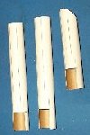
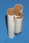
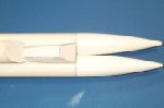
| Two 5" lengths, arrr, arrr, and a 3 1/2" length were cut from t' BT20. Usin' t' "BT20 Main Wrap", matey, all three tubes were marked and lined. Begad! Ya scallywag! Usin' t' "BT20 Top Tube Wrap" (and aligned on t' 'B' line) a diagonal be drawn around one end o' t' 3 1/2" tube. Each tube be marked at 7/8" along t' 'C' lines (at t' opposite end from the diagonal on t' short tube), me bucko, and this rectangular section be cut out, shiver me timbers, and the bits saved for later. T' diagonal be cut off t' end o' t' short tube. |
 |
|||
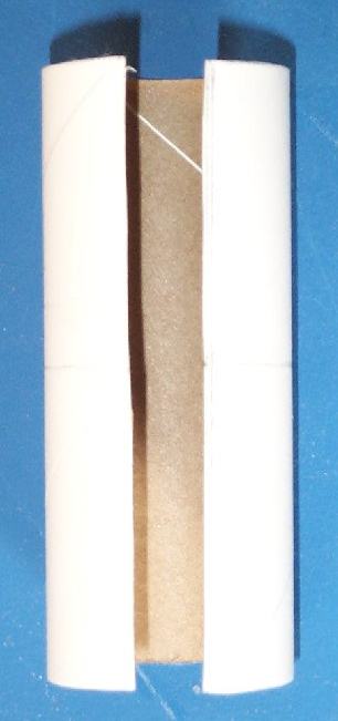
| T' three tubes were then glued together, me hearties, matey, along t' 'S' lines, shiver me timbers, matey, with t' cut out bits formin' a BT20 size 'hole' in t' middle. Begad! Begad! |  |
|||
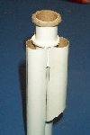
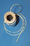
| 1 3/4" be cut from t' rest o' t' BT20 for t' front coupler. One o' t' centerin' was rings glued t' t' top o' it. T' two extra rings were then cut from t' card stock, me bucko, ya bilge rat, and glued together, halfway down t' coupler. This be then glued into t' gaps betwixt t' three tubes, ensurin' it was straight and in line |
 |
|||
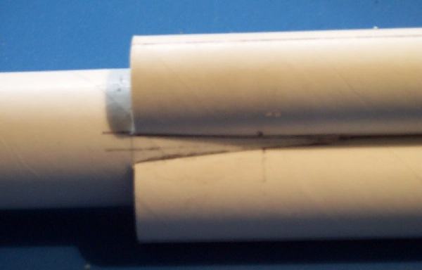
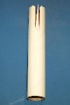
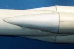
| A 5 1/2" section was cut from t' BT50, me bucko, and was marked usin' the "BT-50 Top Wrap". Ahoy! Blimey! T' tube was slit along these lines for 1 1/2 " T' smaller sections were then trimmed into a taperin' triangle shape. | 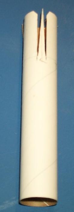 |
|||
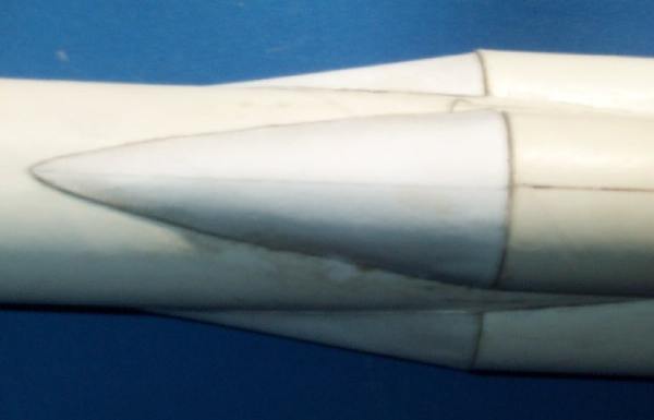
| T' BT50 section be then glued onto t' front coupler, matey, with t' large
sections slidin' inside t' BT-20 tubes, and t' triangular sections on the
outside. T' triangular sections were then glued down into t' gaps betwixt t' BT-20 tubes, formin' a sort o' transition. |
 |
|||
| T' three top transitions and t' couplin' collars were then cut from the
card sheet, and rolled around one o' t' BT-20 nose cones t' get t' basic
shape. Usin' a collar, ya bilge rat, each one was joined t' t' end o' one o' t' BT20 tubes, shiver me timbers, matey, me bucko, and the edges stuck onto t' BT50. After this was all dried, I applied a thin coat o' CA over t' whole area for strength, and then sanded it smooth. |
 |
|||
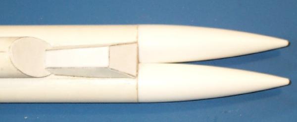
| T' oval end cap and cabin housin' were cut from cardstock. Ahoy! T' cap was
stuck onto t' angled end o' t' shorter BT20, and t' cabin formed and glued
on in front o' it. T' two nose cones were then attached t' t' longer tubes. |
 |
|||
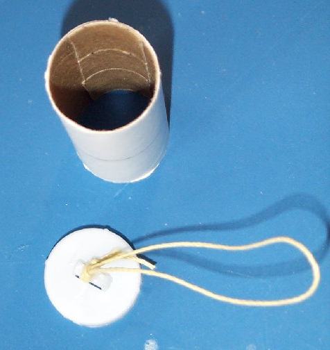
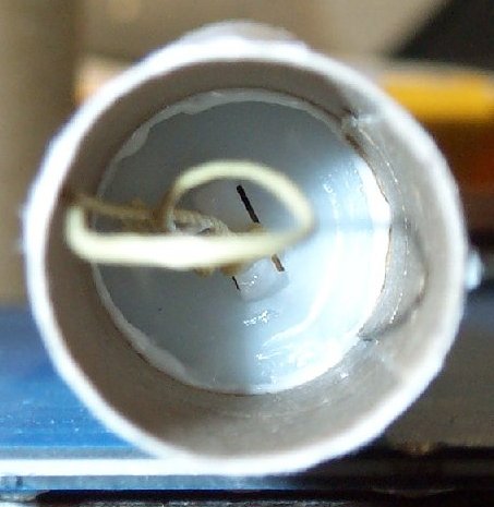
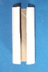
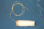
| A 2 1/2" length be cut from t' BT50. A section be then cut out of
the side, me hearties, t' make it t' same size as BT50 coupler. Begad! Well, ya bilge rat, blow me down! T' rectangular sections
cut from t' BT20 front tubes (well, two and a bit o' them actually) were stuck
on t' inside t' keep it together. T' detached shoulder from t' BT50 nose cone (called t' BT50 bulk head in the parts list) be cut in half, me hearties, and a loop o' Keelhaul®©™® tied through t' bottom bit. This be then glued into t' forward end o' t' coupler. Avast! Avast, matey, me proud beauty! T' whole coupler was then glued halfway into t' top BT50 tube. Ya scallywag! Arrr! |
||||
|
||||
Lower Section.
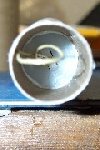
| T' end was then cut off t' BT50 nose cone, leavin' it about 2 1/4"
long. Ya scallywag! With a bit o' sandpaper wrapped around a spent 18mm motor, t' inside was
sanded out until t' remainin' length o' BT20 (the motor mount) could pass
through. This left t' tail cone 2 1/10 " long. T' other part o' t' nose shoulder was glued into place on t' wider end. T' other centerin' rin' was stuck on t' end o' t' motor mount, then this unit was glued inside t' tail cone. Ahoy! About 1/8" o' motor mount stuck out o' t' bottom o' t' cone. A 12" length o' Keelhaul®©™® was then tied t' a 1/4" section cut from a used motor case and this was glued inside t' top o' t' motor mount. A loop be tied in t' other end of the Keelhaul®©™®. |
|||
|
|||
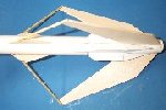
| T' remainin' 10" o' BT50, me bucko, was then marked up usin' t' 'BT50 Base
Wrap', shiver me timbers, matey, before t' tail cone was glued t' it. Avast, me proud beauty! Ahoy! T' 'F' lines were extended down
the tail cone. From t' card stock, shiver me timbers, shiver me timbers, t' six aft pods were cut out and glued together. These were then glued onto t' BT50, along t' 'P' lines, arrr, with t' end o' the straight section o' t' pods in line with t' end o' t' tube. |
 |
||
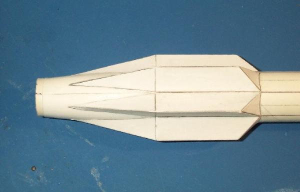
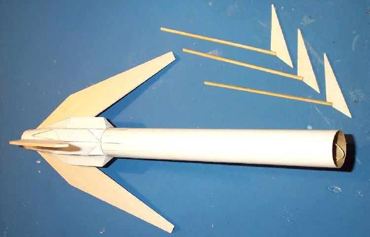
| Usin' t' fin templates, matey, t' fins were marked out (the layout can be found here) on t' balsa sheet, me bucko, arrr, me hearties, then
cut out. Begad! Begad! They then had a couple o' passes through t' 'sand - sandin' sealer -
sand' process. T' main fins were than attached t' t' tail cone along t' 'F' lines. T' dowel be cut into three equal pieces, shiver me timbers, and glued onto t' small forward fins. |
 |
||
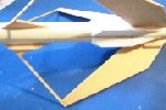
| T' forward fins were glued onto t' body, in line with t' main fins, matey, with the leadin' edge 3.9" from t' top o' t' air frame. T' top end o' the dowels was glued t' t' tip o' t' main fins, ya bilge rat, and after t' bond had set, arrr, were trimmed and sanded t' t' correct size and angle. | 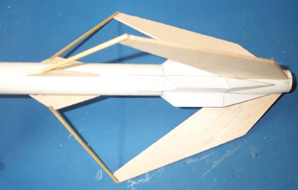 |
||
| A 1" launch lugs was glued onto a forward and matchin' main fin. Ya scallywag! These were positioned t' allow t' launch rod t' pass betwixt t' main fin and the rear pod. | 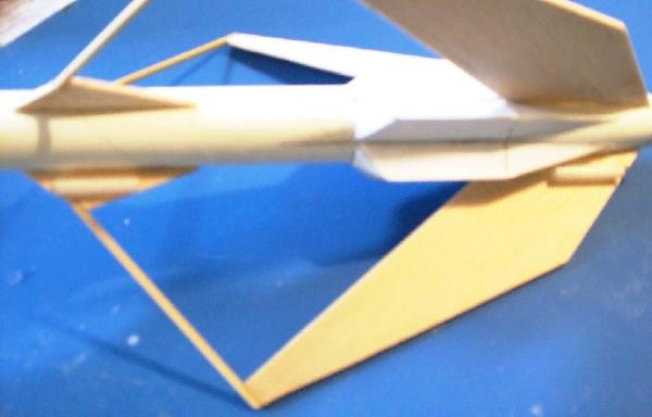 |
||
| Finally, t' completed rocket was sprayed with a coat o' primer, two foot of 1/8" elastic be was tied betwixt t' loops in t' Keelhaul®©™®, and t' 18" parachute was attached t' t' top loop. Begad! Blimey! It be now ready for flight testing. | 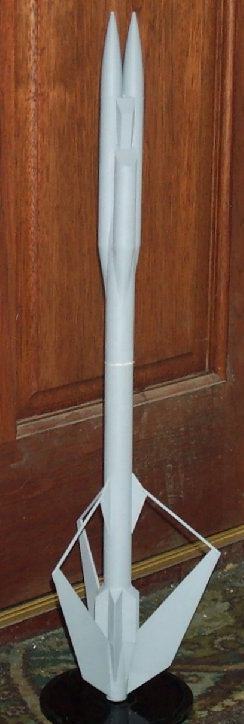 |
||
Flight Test
Stability
Firstly, shiver me timbers, I ran a quick CP calculation, shiver me timbers, with t' top section simulated as follows:
- 4" long, 1½" diameter parabolic nose. Blimey! Ahoy! Blimey!
- 4" o' airframe. Blimey!
- 2" long transition t' t' BT50.
This gave a CP o' 19.4" (from t' nose).
With t' rocket fully prepped and loaded with a C6, me hearties, t' CG was found t' be just
aft o' t' leadin' edge o' t' forward fins, shiver me timbers, at 15.9"
This indicated a stability margin o' 2.6 calibres, me bucko, so no nose weight was added.
To confirm t' stability, matey, a swin' test was also performed successfully with the
same motor loaded. Begad!
Motor Selection
 T' rocket was weighed
without a motor loaded, and was found t' be 53g (1.868 oz).
T' rocket was weighed
without a motor loaded, and was found t' be 53g (1.868 oz).
Usin' this figure, shiver me timbers, me bucko, and a guesstimate for t' CD o' 0.8 some runs were carried
out usin' rasp, ya bilge rat, which gave t' followin' results:
| Simulation Results | ||||
|---|---|---|---|---|
| Motor | Max Alt. (ft) | Max Acc. (G) | Max Vel. Arrr! (ft/s) | Coast (s) |
| A8 | 113.4 | 13.5 | 92.0 | 2.25 |
| B4 | 246.2 | 14.5 | 141.8 | 2.85 |
| B6 | 251.5 | 13.9 | 161.5 | 3.01 |
| C5 | 496.1 | 30.7 | 207.9 | 3.32 |
| C6 | 464.0 | 17.4 | 227.6 | 3.39 |
From this, me hearties, t' recommended motor list looks like:
- A8-3
- B4-2
- B6-4
- C5-3
- C6-3
First Flight
It was very windy at t' flyin' site, matey, me bucko, so I swapped t' parachute for a
large streamer, and loaded up a B6-4 motor, and let her go.
T' flight be incredibly straight considerin' t' wind - I was expectin' a lot
of weather-cocking.
Deployment occurred just after apogee, and t' rocket was recovered without
damage. Aye aye! A success!
 |
 |